- What Is a Gear Pump?
Gear pumps are used in a variety of industries to handle liquids. They offer high flow rates and accurate metering, circulation, and dosing capabilities.
These pumps rely on internal or external gears to rotate, with fluid trapped between cavities in the teeth of each gear. They can also be designed as helical or herringbone gears, and may have a crescent seal.
- Gear Pump Definition
A gear pump is a positive displacement (PD) rotating pump that pumps water or fluid. It is a type of pump used in many industrial applications because it can pump high viscous liquids that cannot be pumped by centrifugal pumps.
This type of pump has a simple and compact design with few moving parts. It is also easy to use and maintain.
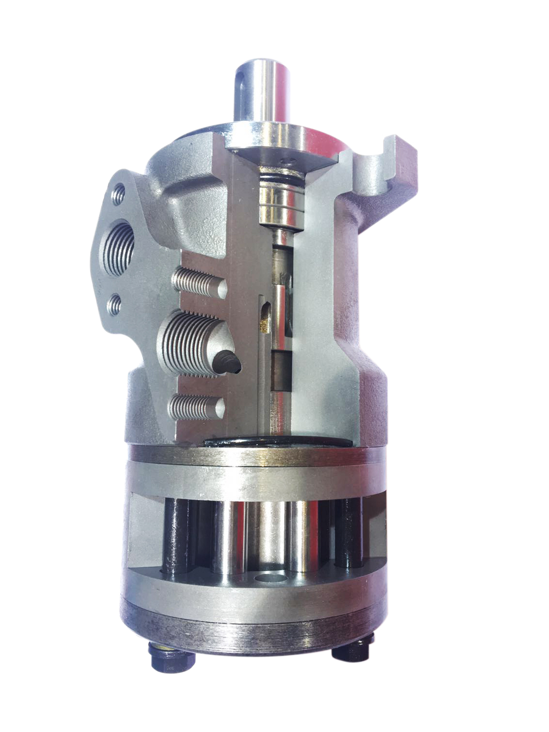
The fluid enters the pump through an inlet port and flows into the cavities between the idler gear and rotor gear. This process causes a partial vacuum at the inlet and the fluid exits through the outlet port..png)
- Gear Pump Types
Gear pumps can be designed in two basic ways. One design utilizes two identical gears that mesh side by side (external gear pump).
The other design consists of one gear placed within another. This design is called an internal gear pump.
The external design allows for higher pressures and flow rates as it has closer tolerances and stronger shaft support. It is able to handle aggressive fluids, such as sodium hypochlorite, sulfuric acid and ferric chloride..png)
- Gear Pump Theory of operation
Invented around 1600 by Johannes Kepler, the gear pump is a type of positive displacement pump that transfers a pulse-less flow directly proportional to its rotational speed. It is a preferred option for transferring high-viscosity liquids such as adhesives, fluid fuels, and motor oils.
A power or driver gear meshes with a driven or idler gear, which is attached to a drive shaft and rotates in the same direction as the driving gear. The two gears then produce a vacuum on the suction side, which forces a fluid into the gear.
This blocked fluid is then transported by the gear teeth as they turn, allowing the fluid to flow from the inlet to the outlet side. This process is repeated for each gear, and as the gears continue to rotate, they generate a pressure difference at the pump outlet.
- Efficiency
Efficiency is the ratio of a pump's flow rate compared to its theoretical drive torque. It's an important measurement of a pump's performance and is often used to evaluate different pump models or brands.
Efficiency can be determined experimentally using a dynamo-meter. It can also be calculated theoretically.
Typically, gear pumps have efficiencies around 85%. This is a function of fluid viscosity, clearance between internal components, friction between mating components and other factors.
In addition to the fluid's viscosity, the gap between the gear teeth and end plates (see figure) also affects efficiency. This gap reduces the pump's ability to hold a pressure difference between inlet and outlet. A small amount of fluid will seep through this gap, causing a slight discrepancy between the amount theoretically carried and the actual amount carried.
- Gear Pump Applications
Gear pumps can be used in a wide range of applications. Typically, they are preferred for high-pressure (5,000-psi) or high-temperature (700°F) applications that require higher flow rates and lower clearances.
They can also be designed to handle viscosities of thousands or millions of cP. However, it’s important to remember that high viscosity fluids can cause a number of operational problems such as cavitation.
In most internal gear pump designs, a crescent seal separates the rotor and idler gears. This keeps the two gears separated and reduces eddy currents that can occur when the gear teeth mesh.

 中文
中文 English
 Español
 Français


